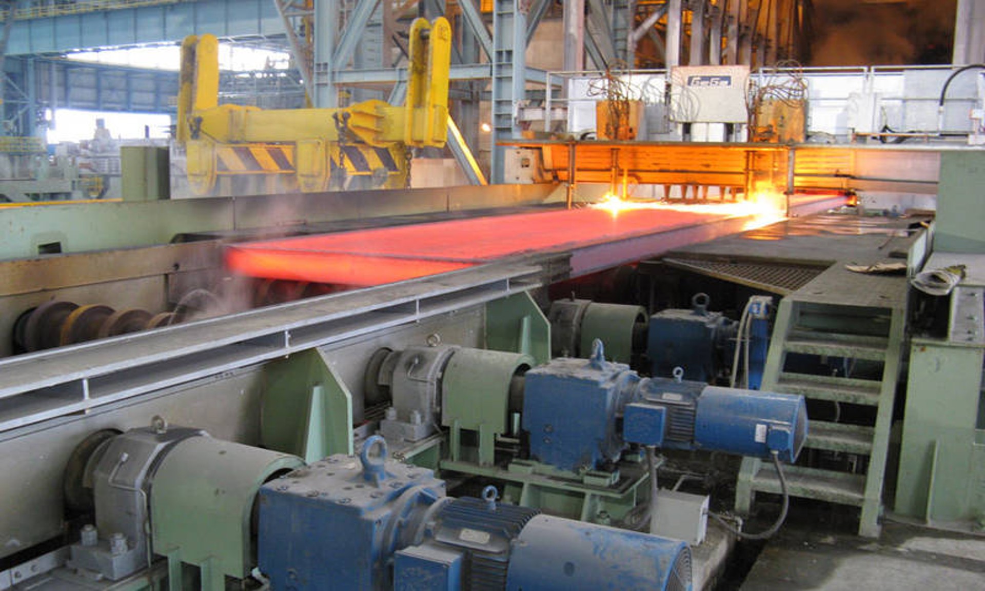




What Is the Synchronous Motor? A Complete Guide to Its Function
A synchronous motor belongs to the category of alternating‑current (AC) electric motors. Its rotor spins at the exact same rotational speed as the rotating magnetic field generated by the stator. That means it runs at a steady speed locked to the frequency of the AC power supply. Fundamentally, the rotor magnetically locks into step with the stator’s rotating magnetic field, which makes it highly suitable for scenarios demanding precise speed control.
Many people know electric motors turn electricity into mechanical motion, yet few are aware of the wide variety of motor designs built for this purpose. Though it may seem unnecessary to develop multiple solutions for one task, engineers have solid practical reasons. Some motors run on direct current (DC), some on alternating current (AC), and others work with both, each adopting unique energy‑transfer mechanisms. Consequently, numerous DC and AC motor types exist, and each brings distinct advantages for specific working conditions.
Synchronous motors are a special group of AC motors developed to overcome the shortcomings of induction motors — another widely‑used AC motor type. As the name suggests, induction motors rely on electromagnetic induction to produce mechanical rotation. Their key disadvantage is slip: a speed gap between the oscillation frequency of input AC power and the actual rotational frequency of the rotor, which is an unavoidable outcome of induction‑driven rotation. Slip is acceptable for most ordinary uses, but it prevents induction motors from delivering accurate timing performance, hence they are called asynchronous motors.
By contrast, a synchronous motor’s output rotational frequency perfectly matches the input AC frequency. Its rotating speed keeps a strict proportional relationship with supplied AC power, so it can be applied in clocks, rolling mills, record players and other equipment. While synchronous motors cannot match induction motors in power output or model diversity, they occupy an irreplaceable position in projects requiring strict timing and accurate rotational speed.
Key Components of a Synchronous Motor
Multiple vital parts work cooperatively to guarantee stable and efficient operation. The main components and their functions are listed below:
- Stator
As the stationary portion of the motor, the stator is assembled from silicon‑steel laminations with inner slots for holding windings. Its core function is to generate the rotating magnetic field for motor operation. - Stator Winding
Generally made of heavy‑duty enamelled copper wire, the stator winding is configured in three‑phase star or delta connection and fitted inside stator slots. Energized by three‑phase AC input, it produces the rotating magnetic field. - Rotor
This is the rotating part of the motor. It has a cylindrical structure with magnetic poles on its outer surface. Like the stator, it is built with silicon‑steel stampings to improve magnetic performance and cut energy loss. - Rotor Winding
Enamelled copper wire is wound around rotor poles to form the rotor winding. Supplied with DC power from the exciter, it creates a fixed magnetic field so that the rotor can lock onto the stator’s rotating magnetic field. - Exciter
Mounted on the same shaft as the rotor, the exciter is a small‑capacity DC shunt generator. During motor operation, it outputs DC excitation current for the rotor winding and forms a self‑sustaining excitation supply. - Slip‑Rings and Brushes
Two phosphor‑bronze slip‑rings are installed on the rotor shaft. Carbon brushes keep continuous contact with slip‑rings, transmitting DC excitation current from the exciter to the rotor winding for smooth, reliable power transfer.
Main Characteristics of Synchronous Motors
- Synchronous motors cannot start by themselves. Auxiliary external driving force is required to bring rotor speed close to synchronous speed before magnetic synchronization can take place.
- Its running speed is locked to power‑supply frequency. With fixed input frequency, it maintains constant rotational speed regardless of load variation.
- It features adjustable operating power factor, a unique property that enables it to improve overall system power factor.
Applications of Synchronous Motors
- Capable of operating under leading or lagging power‑factor conditions. When running with no load, it works at leading power factor, so it can be deployed in power grids where static capacitors are not feasible for power‑factor correction.
- Suited for low‑speed, high‑power working conditions. Typical equipment includes mills, chippers, agitators, pumps and compressors.
How Does a Synchronous Motor Work
Similar to slip‑ring induction motors, a synchronous motor consists of an outer stator and an inner rotor, and generates output torque through magnetic interaction. Depending on size and application, it can run on single‑phase or multi‑phase AC input.
Its stator shares the same structure as induction motors: copper or aluminium coils embedded in laminated metal sheets. AC flowing through these coils generates a rotating magnetic field. The major difference lies in the rotor, which carries a permanent‑like magnetic field produced either by physical permanent magnets or DC‑energized rotor coils. Equipped with fixed north‑south magnetic poles, the rotor will align its poles with those of the stator rotating magnetic field, producing rotation speed strictly proportional to stator supply frequency. Rotor poles can protrude outwards or be embedded inside slots, corresponding to salient‑pole rotors and non‑salient‑pole rotors respectively.
External excitation assistance is essential for startup. At standstill, the stationary rotor cannot lock magnetically with the fast‑spinning rotating magnetic field. Based on excitation modes, synchronous motors fall into two categories: non‑excited synchronous motors and current‑excited synchronous motors.
Working Principle
A synchronous motor is a double‑excitation machine that receives two separate electrical inputs. Its stator winding takes three‑phase AC power, while its rotor winding receives DC power. Three‑phase current in stator windings generates a rotating three‑phase magnetic flux; DC fed into the rotor creates a steady constant flux.
At one instant, rotor and stator poles may have identical polarities and produce repulsion; in the next instant they become opposite poles and generate attraction. Held back by rotor inertia, the stationary rotor cannot turn under alternating attractive and repulsive forces. This explains why synchronous motors are non‑self‑starting.
Auxiliary mechanical means are used to spin the rotor in the same direction as the rotating magnetic field and bring its speed near synchronous speed. Once synchronous speed is achieved, magnetic locking takes effect. Even after removing the auxiliary driving mechanism, the motor keeps rotating steadily.
Types of Synchronous Motors
Classification is based on how rotors obtain excitation to reach synchronous speed: non‑excited synchronous motors and current‑excited synchronous motors.
Non‑excited Synchronous Motors
They need no external excitation voltage for startup. Their rotors use ferromagnetic materials to interact with the stator magnetic field. Three major subtypes are hysteresis motors, synchronous reluctance motors and permanent‑magnet motors.
- Hysteresis motors: A non‑magnetic rotor shaft is wrapped by a ferromagnetic hysteresis ring. The stator rotating magnetic field induces magnetic poles in this ring. Due to hysteresis loss from magnetizing‑demagnetizing cycles, rotor magnetic flux lags behind stator flux. Such phase offset creates angular displacement between two magnetic fields and yields output torque. These motors run quietly and are widely used in record players, tape recorders and other audio devices.
- Synchronous reluctance motors: They produce motion relying on magnetic attraction and reluctance effect. In structure they resemble stepper motors and induction motors. The stator has coil‑wound salient poles to build magnetic fields. The ferromagnetic rotor is structurally modified from squirrel‑cage rotors, featuring grooves and magnetic barriers. When rotor and stator poles align, magnetic flux passes through low‑reluctance paths; when misaligned, flux paths lengthen and magnetic reluctance rises. Reluctance torque is produced as the rotor tends to return to low‑reluctance aligned positions. Some designs can pull the rotor into synchronous speed for precise rotation output.
- Permanent‑magnet motors: Rotors are fitted with permanent magnets to supply constant magnetic flux. Interacting with the stator rotating magnetic field, they deliver rotational output. Variable‑frequency drives are mandatory for speed and torque adjustment, since speed can only be changed by modifying stator AC supply frequency.
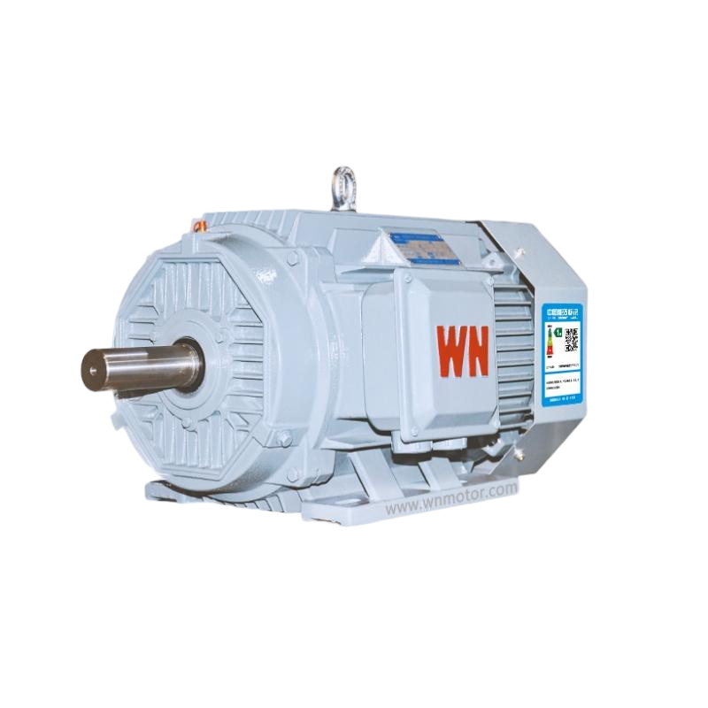
Current‑excited Synchronous Motors
The dominant type is the DC‑excited synchronous motor, which requires both AC and DC inputs. DC power feeds into rotor windings (similar to stator windings) and builds a steady magnetic field. This excitation enables pole alignment with the stator rotating magnetic field to realize synchronization. Most motors above 1 horsepower belong to this type, and they are what people commonly refer to when talking about synchronous motors.
Synchronous motors are irreplaceable for many devices: clocks, record players, windshield wipers, hard disk drives, signalling hardware, recording instruments and timing‑related equipment all depend on them. Besides accurate speed performance, they help offset induction motor energy waste and reduce power‑distribution losses. Though more costly and complex than induction motors, synchronous motors offer great value for industry in power‑factor adjustment and high‑precision operation, serving as a powerful option for equipment designers.
Summary
This passage introduces what the synchronous motor is, its internal structure, operating principle, classification and real‑world applications.